


QFP144_to_DIP_adaptor_2_Rev_A
Design by: fmuntean
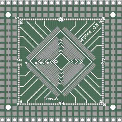
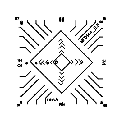
QFP144 is a prototype board that support ICs with 32, 48, 64, 80, 100, 144 pins with a 0.5mm pitch.
On the internet could only find adapters that will transfer all pins out and no place to put any other components like small decoupling capacitors or anything for that matter.
No circuit requires all pins to be surfaced however with this board there are plenty of opportunities:
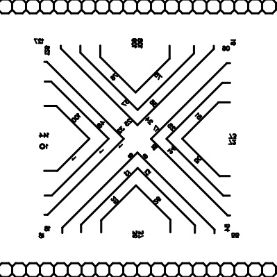
There are two DIP lines with 25 pins each that will accept regular headers.
On the other sides is possible to solder up to 2x20 pin headers thus allowing for another 80 pins to be surfaced
This allows for surfacing 130 pins out of the maximum 144 pins when using the biggest chip
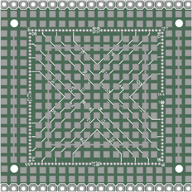
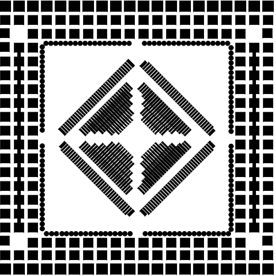
All the pins are wired in such a way that allows for mounting decoupling capacitors on the bottom side for every pin. Also a 0 ohm resistor can be wired to the ground which is the inside square on the bottom.
Currently none of the pins are wired which allows for remapping of the pins as the user sees fit.
All the vias are design with soldering in mind and 30 gauge (wrapping wire) can be soldered to them providing an easy way to bring the pins to the border. Also you will find them very usefull when testing the soldering of the ICs on the board.
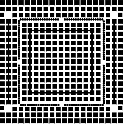
The center zone on the bottom of the board allows for a 15x15 surface mount prototype soldering surface. As this is on the bottom the board will look neat from above when mounted. :)
The ground traces on the bottom side are plated allowing for increasing the surface using solder if they are used as ground and also at the same time they are thin enough to allow for cutting them in order to use more prototype surface.
There are 4 holes for mounting the board.
There are guiding lines on the top to allow for easy detection of the lines when smaller ICs are used.